
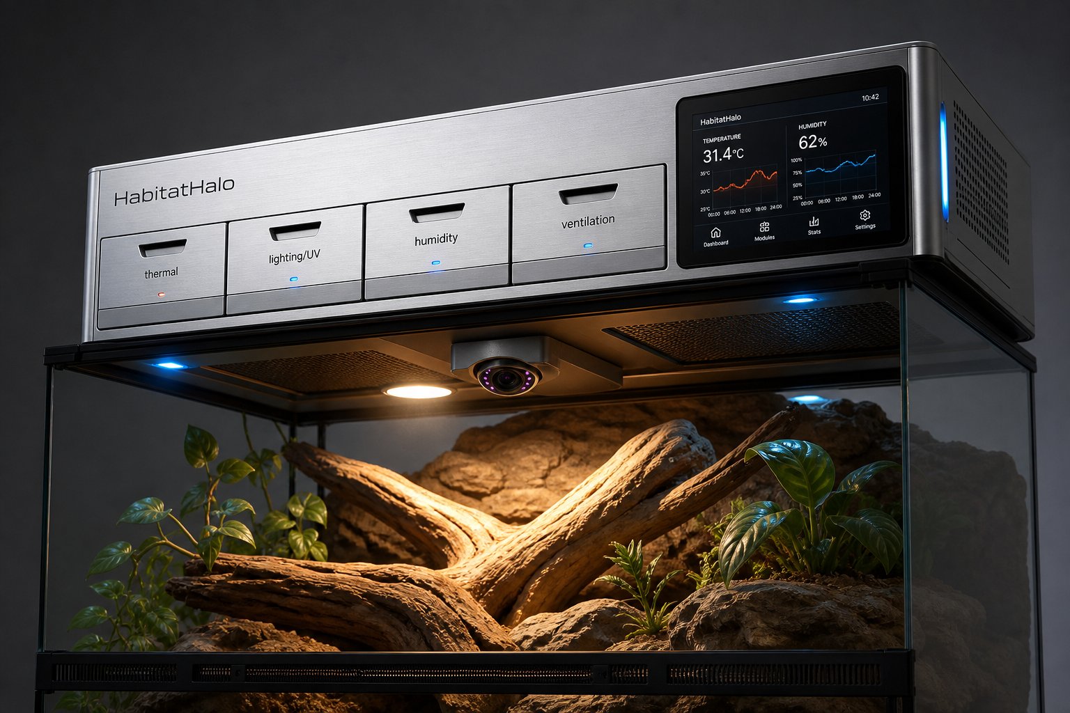
A Romeo Foundation product. Perpetual Revenue Covenant: 100% of all HabitatHalo revenue is permanently directed to the Romeo Community Housing Initiative Foundation, which owns all associated intellectual property. Every purchase supports housing and community programs.
Concept renders — all angles
Tap any image to bring it up full-size with a fuller description. These are concept renders of the proposed working product, not photographs of a finished unit.
Eight-segment exploded assembly
Every size shares the same stack, top shell to adapter layer. Only the footprint and bay count scale. Tap any segment to see what it is, why it is specified that way, and why it sits where it does.
Power & data block diagram
How power is distributed and where the data flows. SelfSense™ diagnostics watch every rail.
Mains / PoE++ in
Facility or wall supply
PSU + fusing
SelfSense™ monitors every rail
Proposed engineering targets pending bench validation.
Safety-first wiring architecture
Two separate controllers keep the animal's core protections in force no matter what the software does.
Safety MCU (STM32G071)
Independent controller for heaters, fans and pump with its own watchdog, dual-sensor plausibility checks, zero-cross TRIAC switching and force-guided relay disconnect. Drops power within ~10 ms on a hatch-interlock trip.
Host MCU (ESP32-S3)
Runs the touchscreen UI, local database and Wi-Fi/BLE. It is isolated (SPI/UART with CRC-16) and cannot override the Safety MCU.
Protective hardware
72 °C thermal fuse, high-limit thermostat, dual force-guided relays, fused mains inlet with GFCI/RCD, and full mains / low-voltage / wet-side isolation.
SelfSense™ diagnostics
Continuously monitors every power rail and reports faults to the app.
AutoFit environment scan
On install and continuously after, the unit reads the real enclosure and calibrates care to it — a five-stage scan-to-care loop. Care behaviors remain pending professional veterinary review.
Scan
IR + LiDAR + camera sweep the enclosure
Model
Builds a 3-D + thermal spatial map
Fit
Recommends size + adapter set
Calibrate
Sets set-points to real hot/cool zones
Care
Continuous monitoring; loop repeats
| Scan sensor | Spec (target) | Role in scan |
|---|---|---|
| Thermal IR camera | 160×120 microbolometer, ±0.5 °C | Locates real basking / cool zones |
| ToF / LiDAR depth | 0.1–4 m, ±1 cm | Measures internal dimensions & volume |
| Visual camera | 1080p, 850 nm IR ring, pan-tilt | Substrate / water-feature recognition |
| Environmental mast | Temp / RH / VOC / CO₂ / lux / UV | Baseline atmosphere calibration |
Universal adapter system
Five fixed canopy sizes plus four adapter families cover every enclosure from a 10-inch desktop tank to a 120-inch+ zoo exhibit — with overlapping ranges so nothing falls between sizes.
| Adapter | Adjustment range | Material | Fits |
|---|---|---|---|
| A. Telescoping end-caps (2×) | 0–60 mm per side (120 mm total) | 6063-T5 aluminium + POM slider | Bridges canopy-to-enclosure length gap |
| B. Expandable rim brackets (2–4×) | Rim 4–25 mm thick | Glass-filled nylon, SS thumb-screw | Framed & frameless top rails |
| C. Universal clamps (2–4×) | Jaw 8–55 mm; standoff 20–120 mm | Silicone-lined zinc alloy | Frameless glass, PVC, mesh tops |
| D. Suspension kit (Commercial) | Drop 0.3–3 m, free-span | SS aircraft cable + turnbuckles | Open-top & walk-in exhibits |
Build values by size class
Every size runs the identical AI brain, cassette architecture and SelfSense™ diagnostics — only the physical footprint scales.
| Model | Enclosure fit | Canopy L × D × H | Bays | Max power | Mounting |
|---|---|---|---|---|---|
| HH-S (Nano / Small) | 10–30″ / 10–40 gal | 457 × 152 × 102 mm (18 × 6 × 4″) | 3 | ≤75–150 W | Top-rail or rear-wall bracket |
| HH-M (Medium) | 30–48″ / 40–120 gal | 914 × 203 × 114 mm (36 × 8 × 4.5″) | 5 | ≤300 W | Top-rail or rear-wall bracket |
| HH-L (Large) | 48–72″ / 120–240 gal | 1219 × 254 × 127 mm (48 × 10 × 5″) | 6 | ≤600 W | Rear-wall bracket |
| HH-XL (XL) | 72–96″ / 240–480 gal | 1524 × 305 × 140 mm (60 × 12 × 5.5″) | 8 | ≤600 W+ | Rear-wall bracket + side supports |
| HH-Commercial (Mega / Zoo) | 96–120″+ / 480–720 gal+ | 1829 mm+ × 356 × 152 mm (72″+ × 14 × 6″) | 10 (dual) | Facility-fed | Truss / ceiling / free-span |
All rail pitch 200 mm. Figures are proposed engineering targets pending bench validation.
Bill of materials (core build)
The main components to build one medium unit. Part numbers are real, verifiable engineering selections; confirm live pricing and availability at order time. Camera and IR-ring parts are honest placeholders that are not yet sourced.
| # | Component | Manufacturer | Part number | Qty | Note |
|---|---|---|---|---|---|
| 1 | Dual Temp/RH sensor | Sensirion | SHT41-AD1B-R2 | 2 | Verified datasheet exists; re-check pricing at order time |
| 2 | Non-contact IR temp sensor | Melexis | MLX90614ESF-DCI | 1 | Reads real basking-surface temperature |
| 3 | Safety microcontroller | STMicroelectronics | STM32G071KBT6 | 1 | Independent safety controller |
| 4 | Application MCU board | Espressif | ESP32-S3-WROOM-1U | 1 | UI, local DB, Wi-Fi/BLE |
| 5 | 24 V power supply | Mean Well | LRS-100-24 | 1 | Primary low-voltage rail |
| 6 | 16 A 800 V TRIAC | STMicroelectronics | BTA16-800BW3G | 1 | Zero-cross heater switching |
| 7 | Force-guided safety relay | Omron | G7SA-2A2B DC24 | 1 | Series disconnect for loads |
| 8 | Optocoupler TRIAC driver | Vishay | IL420 | 2 | Mains / low-voltage isolation |
| 9 | 4.3 in capacitive LCD | Waveshare | 4.3inch-DSI-LCD | 1 | Touchscreen UI |
| 10 | 60 mm PWM MagLev fan | Sanyo Denki | 9GA0612P7G01 | 2 | Ventilation / electronics cooling |
| 11 | 24 V diaphragm pump | OEM | FL-2202 24V Mini | 1 | Misting / fluid module; exact OEM to confirm |
| 12 | Thermal cutoff, 72 °C | Microtemp class | G4A01072C | 2 | Verify exact trip temp on chosen part |
| 13 | 6063-T6 aluminum extrusion | Custom | HH-EXT-MED-01 | 1 | Chassis; needs local supplier quote |
| 14 | Camera module (proposed) | TBD | TBD | 1 | Not yet sourced — placeholder, no price fabricated |
| 15 | IR LED ring, 850 nm (proposed) | TBD | TBD | 1 | Not yet sourced — placeholder, no price fabricated |
Proposed engineering selections pending bench validation and licensed-EE sign-off. No prices are fabricated.
Wiring & connection schedule
How the parts connect — the safety-first power and signal paths. This is a schematic-level architecture for review by a licensed electrical engineer before any mains-connected bench test.
| From | Through / protection | To | Notes |
|---|---|---|---|
| Mains / wall supply | Fused inlet + GFCI/RCD (site electrician) | Power supply (Mean Well LRS-100-24) | Mains compartment physically isolated from wet + low-voltage sides. |
| Power supply 24 V rail | SelfSense™ rail monitoring | Safety MCU, Host MCU, fans, pump | Single monitored low-voltage rail feeds all logic and DC loads. |
| Switched mains | TRIAC (BTA16) driven by optocoupler (IL420) | Heater loads (halogen / DHP) | Zero-cross firing; in series with the force-guided relay. |
| Safety MCU (STM32G071) | Force-guided relay coil + TRIAC gate | Heater / fan / pump loads | Drops power within ~10 ms on a hatch-interlock trip. |
| Thermal fuse (72 °C) + high-limit thermostat | Series in the load circuit | Heater loads | Hardware limit independent of any software. |
| Sensors (SHT41 ×2, MLX90614) | I²C bus | Safety MCU + Host MCU | Dual-sensor plausibility check before any heat is allowed. |
| Host MCU (ESP32-S3) | DSI / GPIO | 4.3 in touchscreen, Wi-Fi/BLE, camera | App + connectivity only; never core control. |
| Safety MCU ↔ Host MCU | Isolated SPI/UART, CRC-16 checked | (link only) | Host MCU cannot override Safety MCU limits. |
Do not power a mains prototype without EE sign-off and proper fusing/GFCI protection in place.
Thermal budget (medium unit worked example)
The heat-loss math that sizes the heaters and cooling — so a builder can size parts correctly for a real enclosure.
Example enclosure
Medium 120 × 60 × 60 cm (0.432 m³)
Glass heat loss
≈ 100 W (A 1.92 m², U 5.8, ΔT 9 K)
Mesh heat loss
≈ 78 W (A 0.72 m², U 12.0, ΔT 9 K)
Total heat loss
≈ 178 W
Heater sizing (×1.4 safety)
≈ 249 W → 100 W halogen + 150 W DHP (250 W peak)
Electronics-bay rise
≈ 4 K above ambient (28 W dissipated, ratings not approached)
Thermal barrier
3.0 mm mica-ceramic (UL94 V-0 target, to verify)
All figures are proposed engineering calculations pending bench validation, not verified third-party test results.
Full engineering diagram book
Every segment, adapter mechanism, cross-section and block diagram in one document.
Important disclosures
- HabitatHalo is not a medical device and does not diagnose, treat, cure, or prevent any disease.
- Animal-care guidance is provided for husbandry support only and is PENDING PROFESSIONAL VETERINARY REVIEW. Always consult a qualified exotic-animal veterinarian for health decisions.
- Hardware capabilities described here are PROPOSED ENGINEERING TARGETS PENDING BENCH VALIDATION and are subject to change.
- All prices are planning estimates (“Est.”) and are not an offer of sale. Availability, features, and pricing may change.
Nathaniel Jerome Romeo Fell III · Romeo Community Housing Initiative Foundation · 938 Kalamath St, Denver CO 80204 · (720) 246-1534 · EIN 41-4327332